|
Contents: Introductory Telephone instruments Telephones: No. 301, No. 305, No. 315, No. 320, No. 325, No. 340, No. 345, No. 350, No. 355, No. 360, No. 365, No. 370, No. 375, No. 380, No. 385, No. 390, No. 395, No. 400, No. 405, No. 410, No. 415, No. 420, No. 425, No. 430. Junction switches: No. 435, No. 450, No. 455, No. 460, No. 465, No. 466, No. 468. |
Generators: No. 475,
No. 477,
No. 478. Testing set: No. 485. Combination sets: No. 490-530, Breastplate transmitter: No. 535-540 Accessories: No. 545, No. 547, No. 549, No. 550, No. 551, No. 552, No. 575, No. 576. Connection descriptions. About this material |
Introductory
Therewith we have the honour to present to our esteemed customers and friends the 4th edition of our illustrated catalogue.
During the 5 years which have elapsed since the 3:rd edition was published, a rapid and great development has taken place in the telephonic line and we have always endeavoured to be on a level with the development, a fact, which may be proved by the various new patterns of telephone instruments as well as of switchboards. The more and more extended market which during the course of time has been opened to our products within as well as outside Europe, has caused us to considerably enlarge our works in order to meet the rapid increasing demand. In the future, not less than hitherto7 we shall endeavour to show the accuracy and solidness in the performance, which has had the effect that our articles have been able to cope with the best ones found abroad, and we sincerely hope that our patrons and friends will keep us in mind.
Stockholm, July 1897.
Telephone instruments.
We now manufacture two kinds of telephones, wall-instruments and table-sets and as the following illustrated description will show several patterns of each.
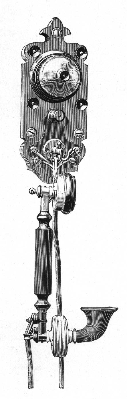
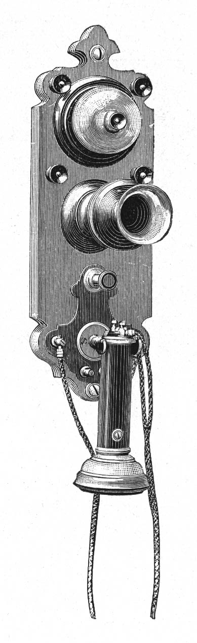
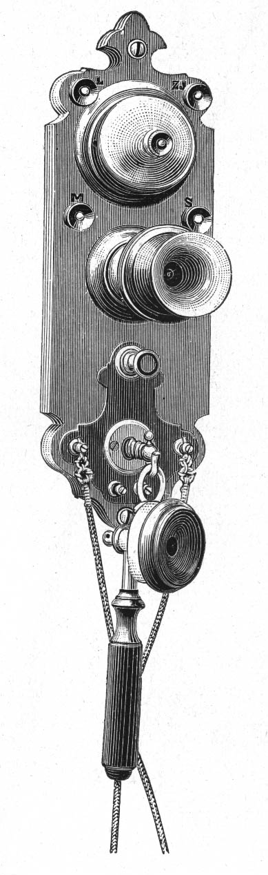
The wall-instruments are made in three different types of which the 'ordinary size', having a generator which rings safely through 20,000 ohms, is the one generally used. The 'large size' being provided with a generator ringing through 25,000 ohms and enough battery space for two large Leclanche cells is especially recommended for interurban traffic. The 'small size' intended for places where the traffic is entirely local has a generator ringing through 5,000 ohms. Finally we make instruments for battery-ringing but are these only supposed to be used for private installations within houses, factories etc.
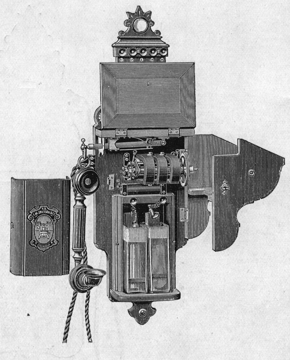
Of all instruments of the 'large size' the covering of the generator, battery box and other details is hinged, thus allowing the chief parts perfectly accessible and the fault-finding consequently is very easy should any such occur [No. 345].
The 'ordinary size' has the battery-box separate from the covering of the generator, which being hinged, may be opened [No. 355].
This is not the case with the 'small size' but on these the battery-box is removable.
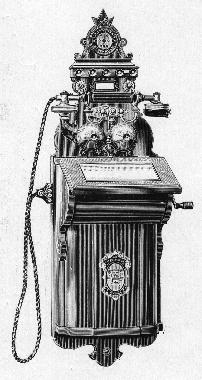
The table sets are made in two types, an ordinary and a smaller and also a special type for battery-ringing. The generator of the larger rings through 20,000 ohms, and two magnets serving as a stand for the instrument and all the principal parts are easily accessible.
The 'smaller size' has the mechanism covered by a removable ornamental case and the generator rings through 5,000 ohms.
All our instruments are provided with our patented carbon grain transmitters, which have the advantage of always being adjusted. These transmitters will be found to be particularly clear at the same time rendering the articulation of the voice extremely distinct which is very desirable when speaking on long lines. They are further provided with a film, which placed in front of the diaphragm, will render them perfectly waterproof, thus preventing any moisture caused by the breath to enter the transmitter or in the least hurt the diaphragm. The best results are obtained when Leclanche cells are used in series.
These cells may be placed in a battery-box of the wall-instruments. For the table-sets they should be placed in a special box at any convenient spot as near the instrument as possible.
The transmitters are either fixed on the instrument - on the table-set on the movable arm - or combined with the receiver making a convenient movable hand-set which of late is made of nickel-plated brass and the terminals are hidden in the handle. To the wall-instrument the combination-set is connected by a four-way cord and plug, which latter fits into a corresponding jack at the left side of the instrument thus rendering the set easily changed.
All wall-instruments, except those used at intermediate stations, are provided with our improved lightning protectors. The table-sets of our latest type is also protected in this way, having the arrester on the wall fitting and here are now also terminals provided for an extra bell.
All instruments are so constructed, that they may be used on either double or single circuits through the connections of the different patterns are varied in several ways as to suit different systems in nearly all parts of the world where our telephones are used.
Instrument for metallic circuits are made to ring on single line as soon as the generator is out in motion, instruments with connections adapted for use on the 'ring through' system having generator calling, but for the ring off signal battery circuits are used.
The different types we are now making may be seen in the following pages. Diagram of connections will be found fig. 1-15. Particulars as to size and weight on page No. 84.
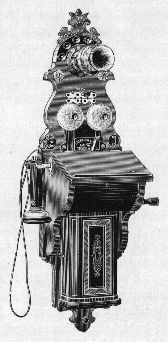
No. 301
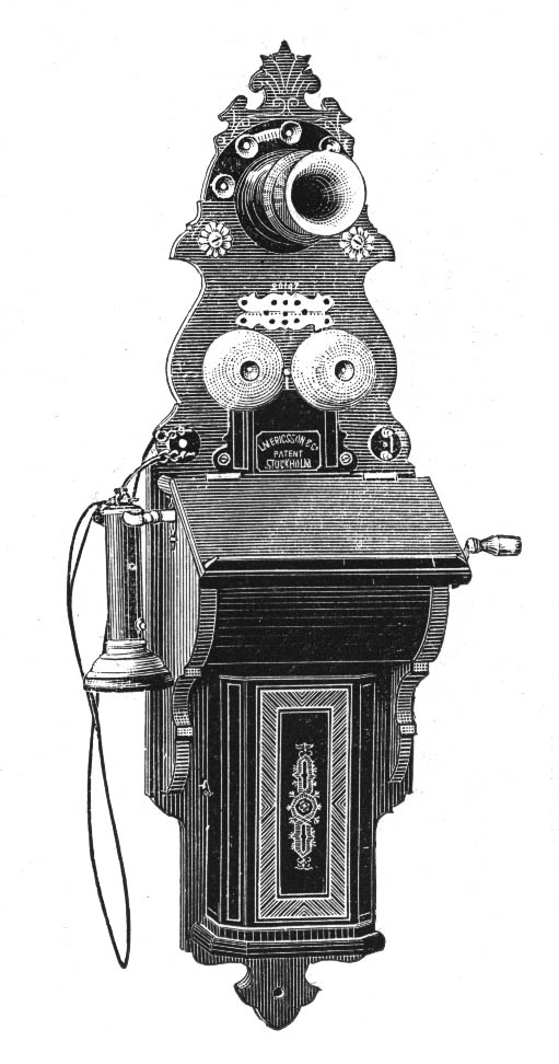
Telephone for terminal stations
Instrument of ordinary size provided with fixed transmitter, a receiver, generator, lightning protector and terminals for the lines, extension bell, an extra receiver and the battery box holding two small Leclanche cells No. 590.
No. 305
Telephone for terminal stations
Small size provided with the same accessories as No. 301, but the generator has two magnets only and the handle receiver is of the same construction as those in the combination set. The cells are placed in a special box, which may be hung under the instrument. The box No. 420 is used.
No. 306
Same as the preceding one [No. 305], but has three magnets to the generator.
No. 310
Telephone for terminal stations
Similar to No. 305, but has a fixed battery-box of the same capacity and appearance as N:rs 301 and 315.
No. 311
Same as the preceding one [No. 310], but has three magnets to the generator.
No. 315
Similar to No. 301, but provided with a writing-tablet in a nickeled frame and a different bracket for the transmitter.
No. 320
Telephone for terminal stations at interurban lines
Large size instrument with four magnets to the generator and battery-space enough for two large Leclanche cells No. 585.
It is further, according to the American system, provided with a key for short-circuiting the bell while ringing, and the secondary of the induction-coil while receiving a message. This prevents noises, made near the instrument, to be heard and makes the resistance less, which will be found an advantage on long lines. The key is only to be depressed while receiving and not so when speaking.
Some practice will be wanted to obtain full advantage of this arrangement.
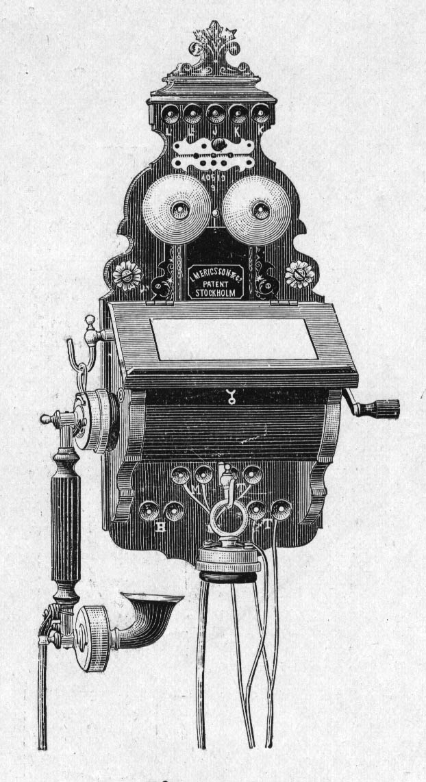
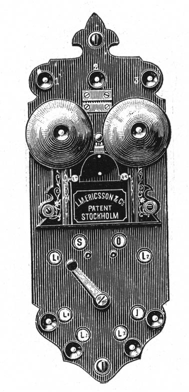
No. 325
Telephone for intermediate stations on single lines
Ordinary size instrument with fixed transmitter and intended for use, where there are several telephones on the same line.
It differs from the preceding instruments in having a switch by which it is possible to get connection with either side of the line in turning the switch to the left or the right. When not in use, the current can pass through whether the switch is turned to the right or left and if in the middle, the bell does not ring for passing signals and it is impossible to listen to the talking from any of the other instruments. It is intended for three single circuits. L’’’ can by a special switch No. 460 be connected to either side of the main line. Diagrams of connections as well as fitting of extension bell will be found Fig 3, 10. Such bells ought rather not to be used to this instrument, but if necessary a high resistance one as No. 426 should be fitted.
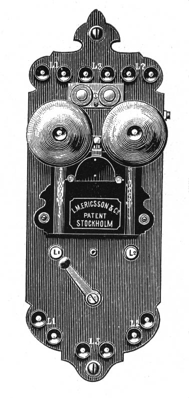
No. 330
Telephone for intermediate stations on metallic circuits.
Large size with combination set, writing-tablet and key for short-circuiting the bell and the secondary of the induction-coil as on No. 320. The bell is shunted across the line and being wound to a high resistance it permits a considerable number of instruments to be connected to the same circuit. The generator is larger than the ordinary ones and gives a high amperage. The instrument is intended for two metallic circuits, but can also be used for two single lines, if the middle terminal is connected to the one on either side of it.
No. 335
Telephone for intermediate stations on metallic circuits.
Similar to the preceding one [No. 330] but fitted for three metallic circuits. To obtain the signal from the third line, if the two others are talking, is necessary to either have a bell shunted on the line, or more preferably to make use of a switch No. 465.
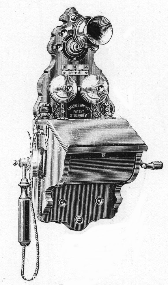
No. 340
Telephone for terminal stations.
Ordinary size instrument with combination-set and writing-tablet but without battery-box. Beneath the cover of the generator are terminals for connecting the battery, the combination-set and an extra receiver.
No. 341
Similar to No. 340 but without writing-tablet.
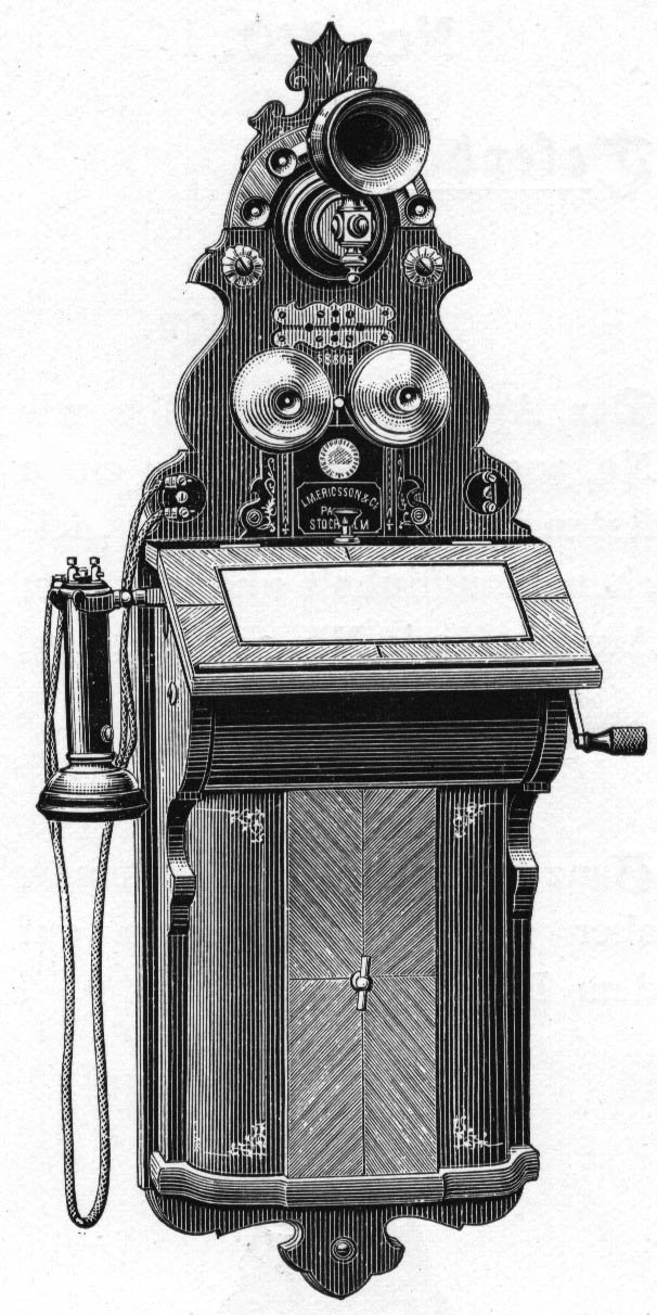
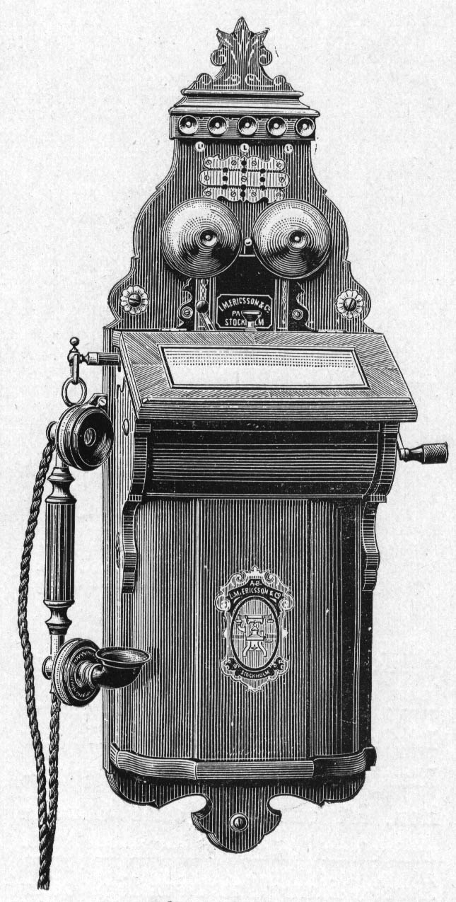
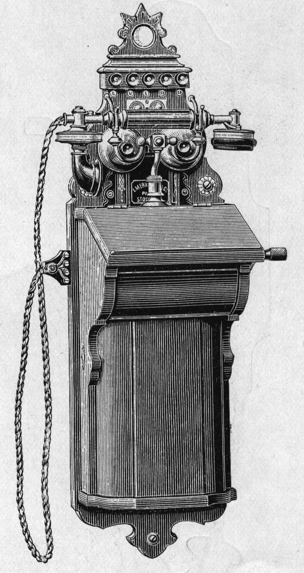
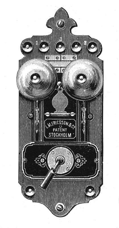
No. 345
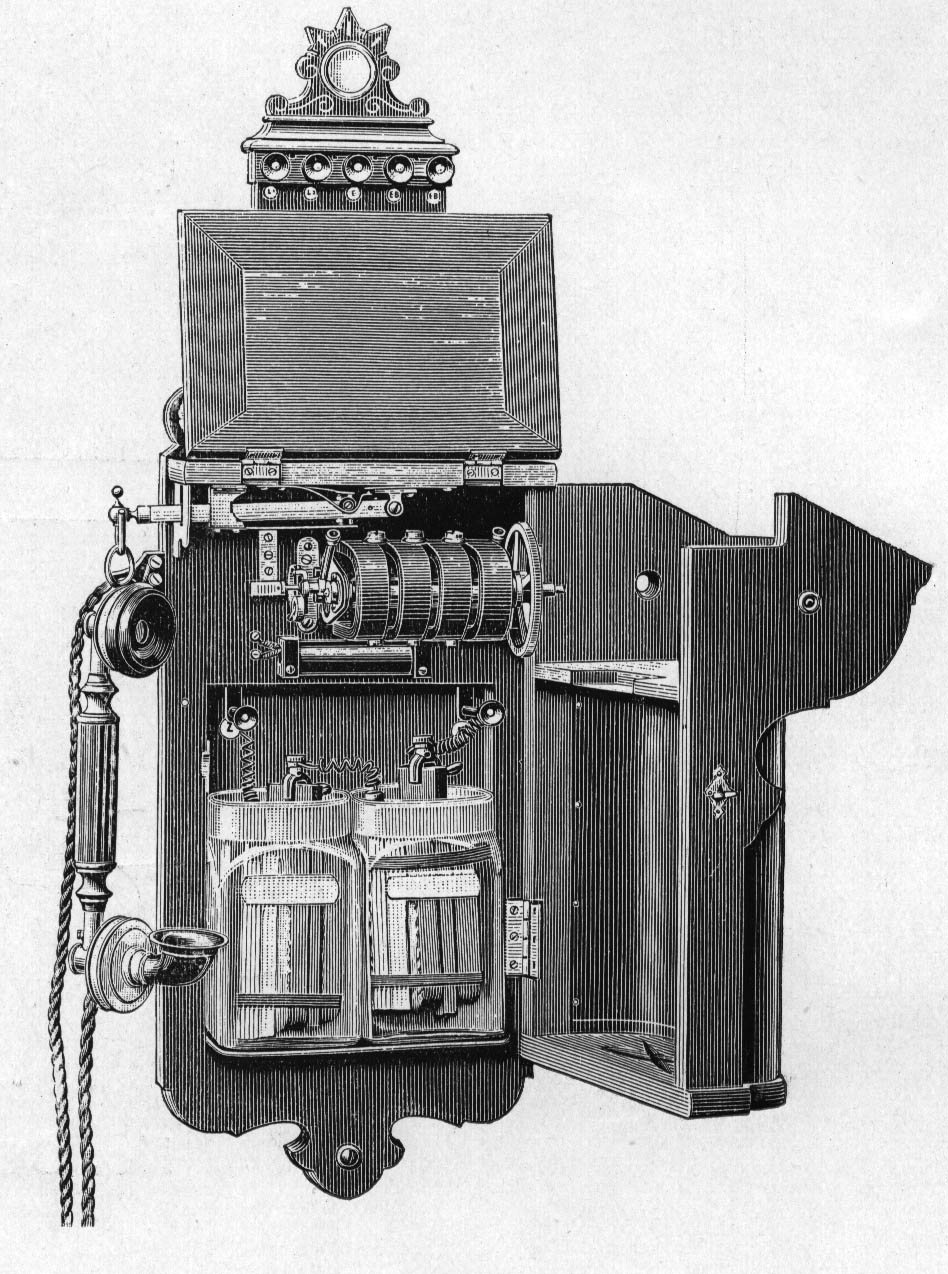
Telephone for terminal stations.
Large size instrument with combination-set and writing-tablet. Like No. 320 it has a key for short-circuiting the bell and the secondary of the induction coil.
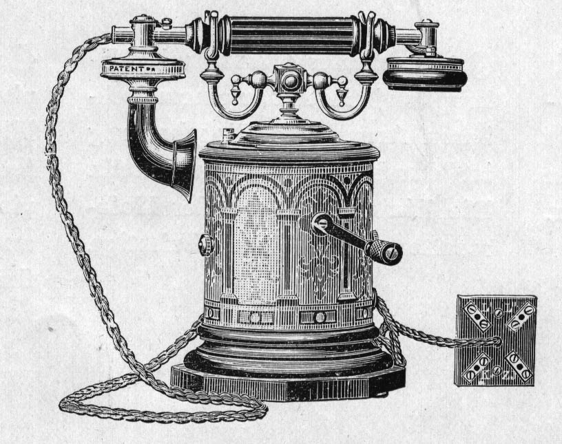
No. 350
Telephone for terminal stations.
Similar to the preceding one [No. 345] but the combination set is lying in the cradle-switch and the lightning protector is of another form.
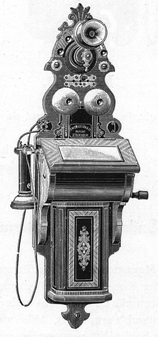
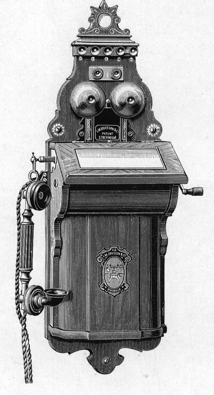
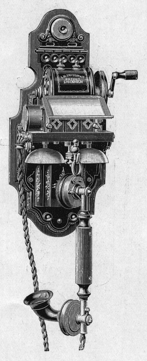
No. 355
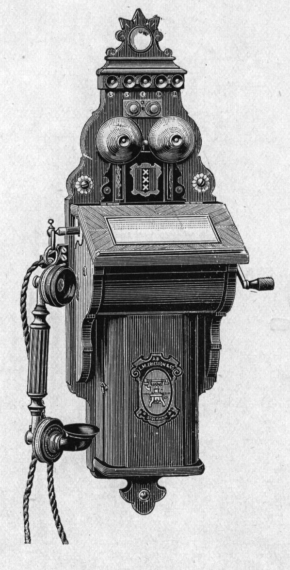
Telephone for terminal stations.
Ordinary size instrument with combination-set and writing-tablet.
No. 356
Similar to the preceding one [No. 355] but without writing-tablet.
No. 360
Telephone for terminal stations.
Though the woodwork is smaller, this instrument belongs to the large size ones, as it is provided with a large generator and room for batteries of the same size as used in the larger instruments.
The combination-set is laying in the cradle switch as in No. 350.
No. 365
Telephone for terminal stations.
In construction this instrument, which is intended for the tropical countries, wood has been carefully avoided as it gets too quickly destroyed by ants and other insects.
The instrument is provided with combination-set and writing-tablet.
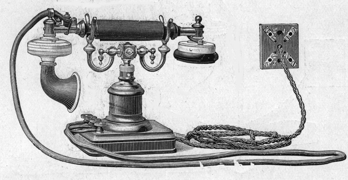
No. 370
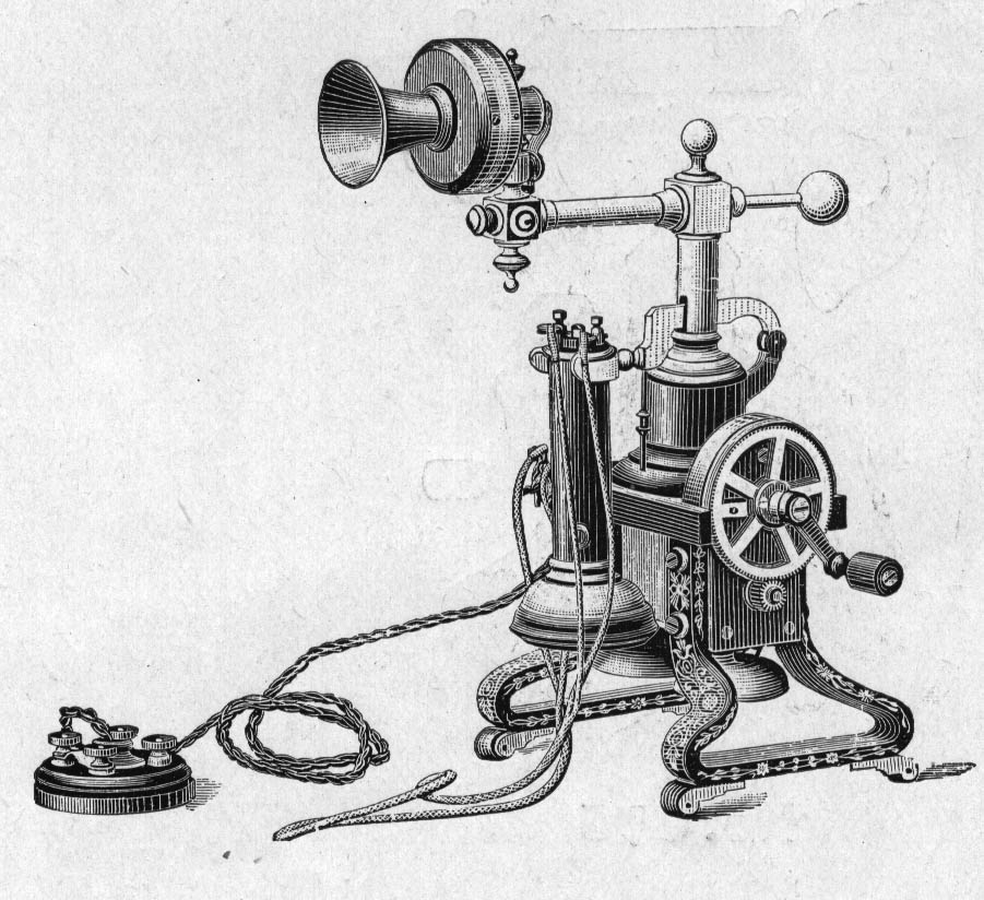
Table telephone-set for terminal stations.
Ordinary size instrument with the transmitter fixed on a mobile arm. The lines are brought to the terminals on the wallfitting as shown in Fig. 11.
No. 375
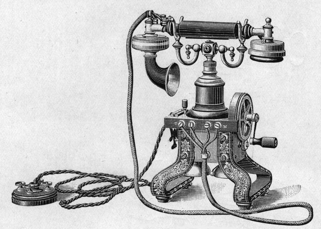
Table telephone-set for terminal stations.
Similar to the preceding one [No. 370] but with combination-set.
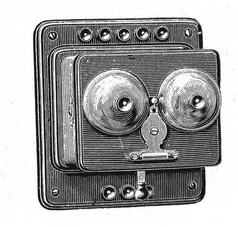
No. 380
Small size with combination-set and the generator covered by an ornamental, easy removable box.
No. 385
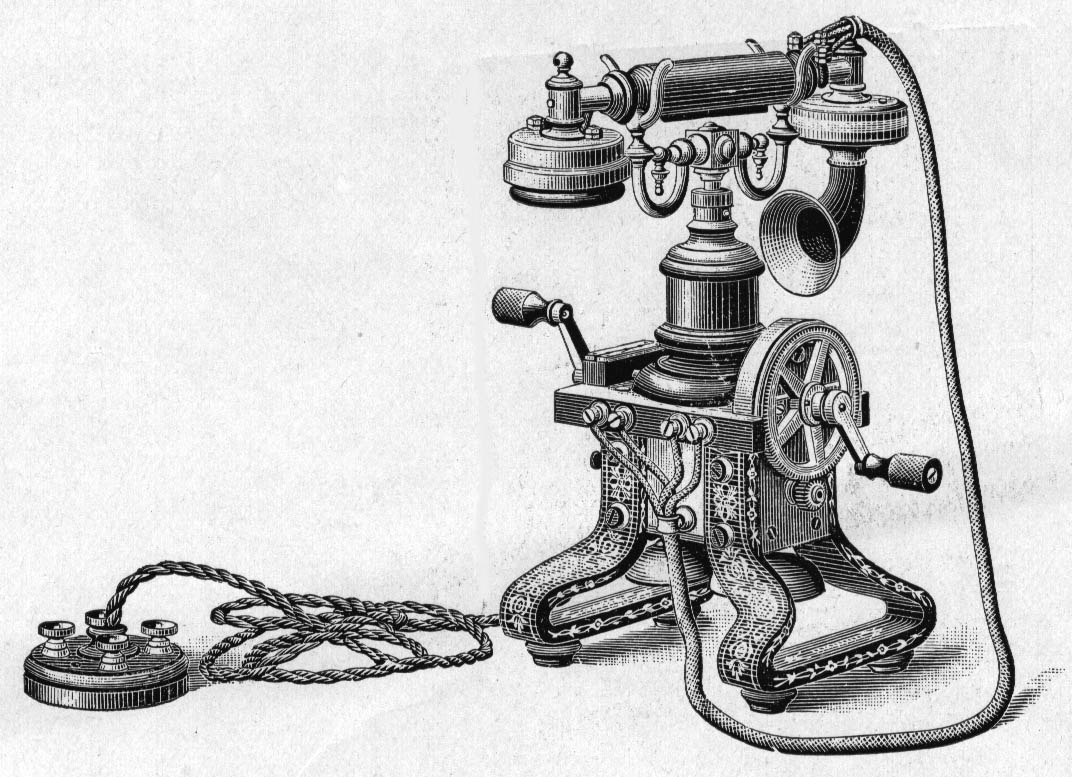
Table telephone-set for terminal stations.
Ordinary size with combination-set. The generator of this instrument is provided with two handles, thus making it particularly suited for writing desks, where two persons are seated opposite each other.
No. 390
Portable telephone for terminal stations.
This instrument may be used for military purposes and at temporary buildings or places where it is often necessary to shift it. It is provided with combination-set, two dry cells, generator, bell, lighting protector and terminals for line and earth. Weight 9,10 ko.
No. 395
Extension telephone without ringing arrangement
This instrument, provided with combination-set, is intended to be placed on a writing-desk, when an extension is wanted to our terminal wall-instruments in another room of the same house, where the signal from the wall instrument can be heard, but it is by this arrangement not necessary to go to the wall-instrument to answer the call. Weight 1,32 ko.
No. 400
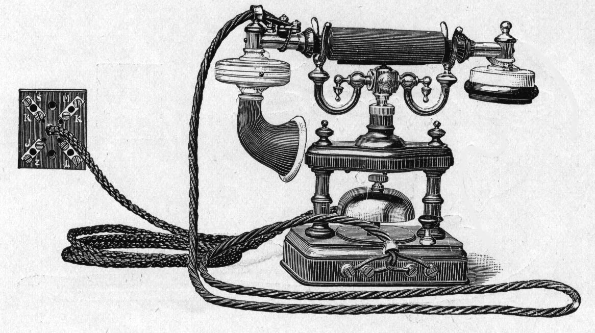
Table telephone-set for battery ringing.
This instrument, as well as the three following ones [No. 405, 410, 415], are intended chiefly for short private lines between offices, for hotels, steamers, factories etc. On such lines this arrangement with the present low price of batteries is the most suitable.
The same accessories are used as to our larger sizes for magneto ringing and the instrument is also provided with induction coil, combination set and a wall-fitting. Weight 1,77 ko.
No. 405
Wall telephone for battery ringing.
Containing the same accessories as No. 400. Weight 1,35 ko.
No. 410
Wall telephone for battery ringing.
Similar to No. 405, but has a fixed transmitter and an ordinary receiver. Weight 1,65 ko.
No. 415
Similar to No. 410, but has a handle receiver of the same as used to No. 305. Weight 1,54 ko.
No. 420
Battery box
to hold two Leclanche cells No. 590.
No. 425
Extension bell.
Having 7 cms gongs and wound to a resistance of 300 ohms, this bell is intended for use in series with the bell of the instrument within houses. Weight 0,9 ko.
No. 426
Similar to No. 425, but wound to 1,000 ohms and generally shunted across the line.
No. 427
Same as No. 426, but wound to 2,000 ohm.
No. 430
Large extension bell
with 11 cms gongs and wound to 300 ohms, it may be used in series with the bell of the instrument. It is provided with a cover for its protection and especially intended for open-air work. Weight 1,50 ko
No. 431
Same as No. 430 but without cover.
No. 432
Similar to No. 430, but wound to 1,000 ohms and generally shunted across the line.
No. 433
Same as 432, but wound to 2,000 ohms.
Junction-switches.
These switches may be used, when one or two branch-lines are wanted in connection with an instrument. As the position of the handle must be altered for each combination, it will be found convenient to use the switch to instruments, belonging to the same person or subscriber. The fitting of an ordinary switch for terminal stations will be found in Fig. 5, 5 and 7.
The handle has three positions viz. for speaking to either line and for connecting the two branch-lines. The switch is provided with a bell, which rings, when signal is given from the line, not in connection with the instrument. To answer this call, the handle is turned over. A signal from the exchange rings the bell on the instrument and this call may be answered without turning the switch. Should the person at the calling instrument wish to be put through, the switch must be turned over and a signal given, after which the switch is left in the middle position. This mode of connection is necessary to prevent a ring off signal being given to the exchange. The switches No. 440, 450 and 455 may also be used for one single and one metallic circuit.
No. 435
Junction-switch
for two single lines. Weight 1,67 ko. See Fig. 5.
No. 440
Junction-switch
for two metallic circuits. It may also be used for one single and one metallic line. When the handle is in the middle, these lines are connected and the B. -line of the metallic is put to earth in the switch. Weight 1,67 ko. See Fig. 6.
No. 450
Junction-switch
for metallic circuits. Provided with a new spring-mechanism. Weight 1,70 ko. See Fig.7.
No. 455
Junction-switch
for metallic circuits. Provided with a new spring-mechanism, easily accessible from the front. Weight 1,95 ko. See Fig. 8
No. 460
Junction-switch
for single lines at intermediate stations.
By this switch a third line may be connected to either side to the main line and also with the instrument. The connection of fitting are shown in Fig. 10. Weight 1,75 ko.
No. 465
Junction-switch
for metallic circuits at intermediate stations. Acting similarly to the preceding one [No. 460]. Weight 1,76 ko.
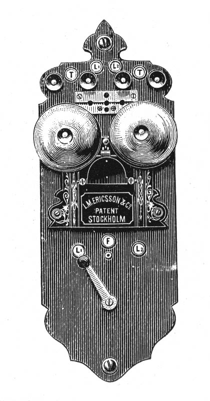
No. 466
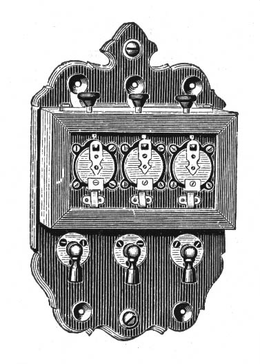
Switch
for three single lines is used in connection with a telephone for terminal station.
The terminal L' on the telephone should be connected with the terminal T on the switch and their resp. J terminals put to the same earth. The three lines should be connected to the terminals on top of the switch.
When speaking from the instrument to any of the lines, the corresponding indicator-shutter should be down and this is most easily done by pressing the button above the indicator. The signal is then given by turning the generator-handle. When the conversation is finished, the shutter should be restored. If for example No. 1 wishes to be connected with No. 3, the corresponding handles are turned horizontally by which means the connections are affected. During the time of speaking, the shutters should be up. At the ring off signal, both shutters drop and are then restored and the handles replaced. When two of the lines are connected, it is possible to speak from the instrument to the third line. Weight 1,20 ko.
No. 468
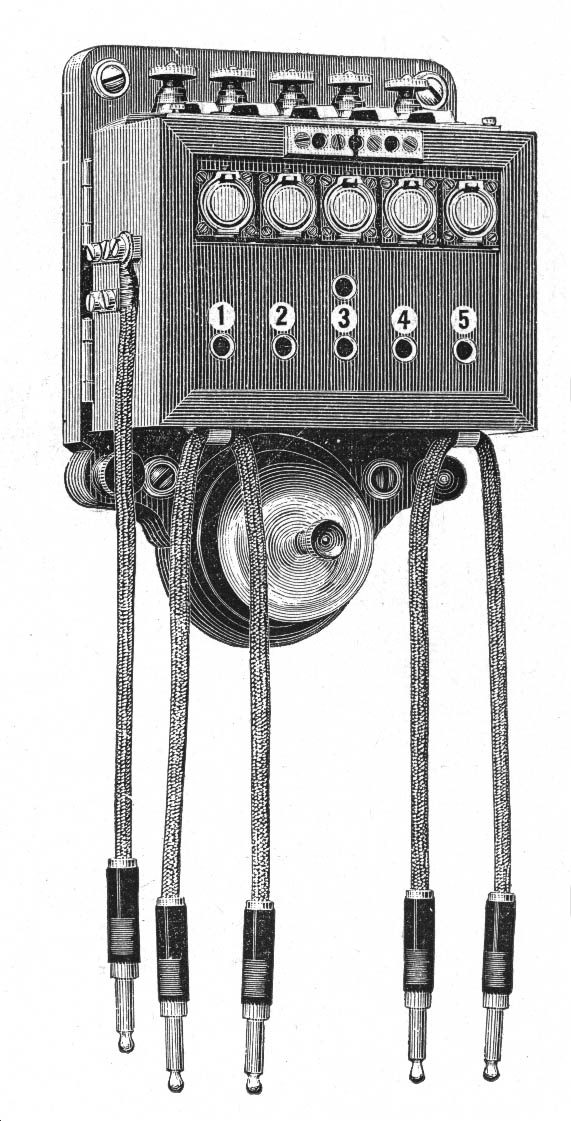
Wall-switches
for single lines.
These instruments should be used in connection with terminal station instruments and may be used both for galvanic and magneto ringing. They arc provided with lightning protectors and with night bell.
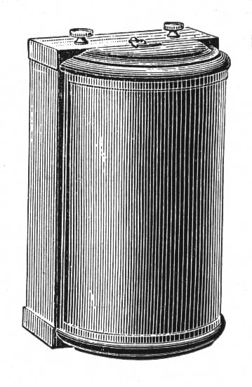
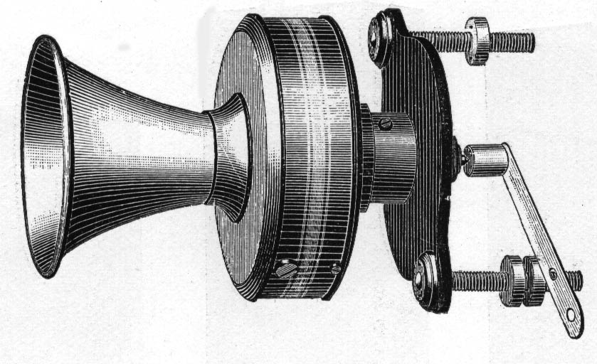
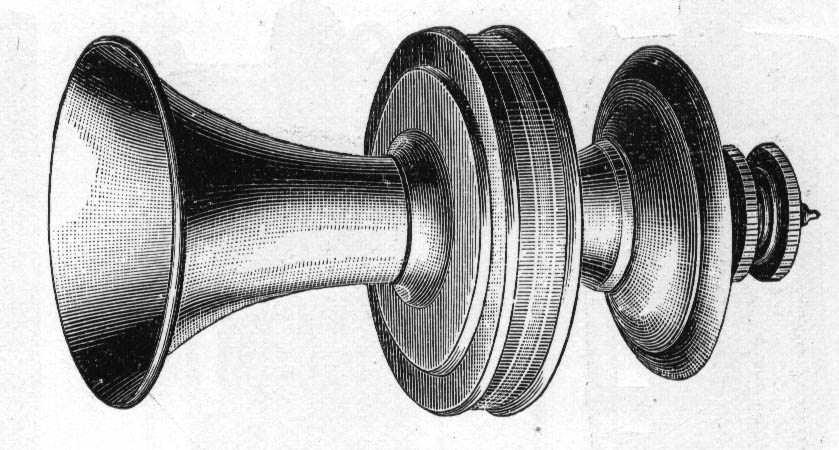
No. 475
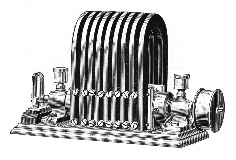
Large generator
to be driven by power and intended for large central stations. If the motive power can not be obtained at the station, the generator may be placed elsewhere and connected by lines with the station. 800 revolutions a minute is the normal speed.
Two types are manufactured, No. 475 giving 60 to 70 volts and 0,6 amperes and No. 476 giving 80 to 90 volts and 0,3 amperes. Weight 11,50 ko.
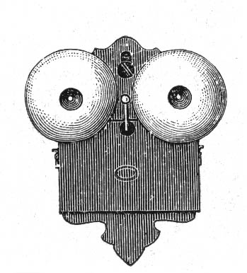
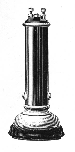
No. 477

Large hand-generator
intended for fire stations or other places, where signalling is required on a large number of bells at the same time. This generator rings through about 30 bells, shunted across the line. Weight 13,50 ko.
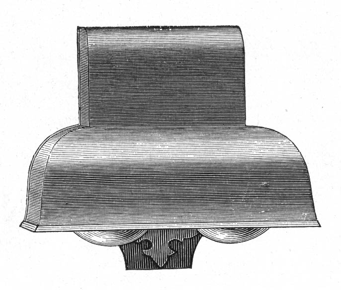
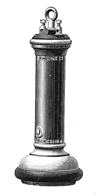
No. 478
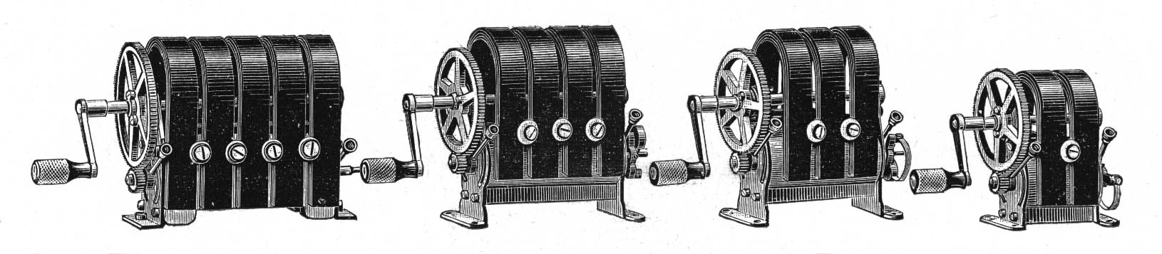
(No. 478, No. 479, No. 480, No. 481)
Hand-generator
with five magnets. Weight 3,60 ko.
No. 479
Similar to No. 478, but with four magnets. Weight 2,36 ko.
No. 480
Similar to No. 478, but with three magnets. Weight 1,90 ko.
No. 481
Similar to No. 478, but with two magnets. Weight 1,26 ko.
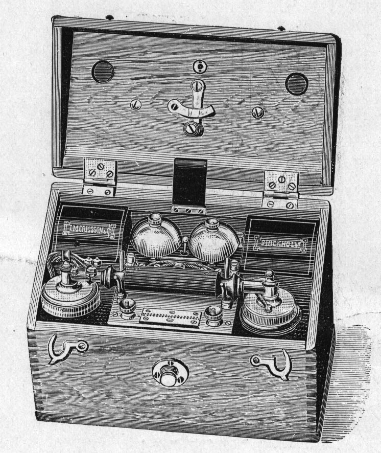
No. 485
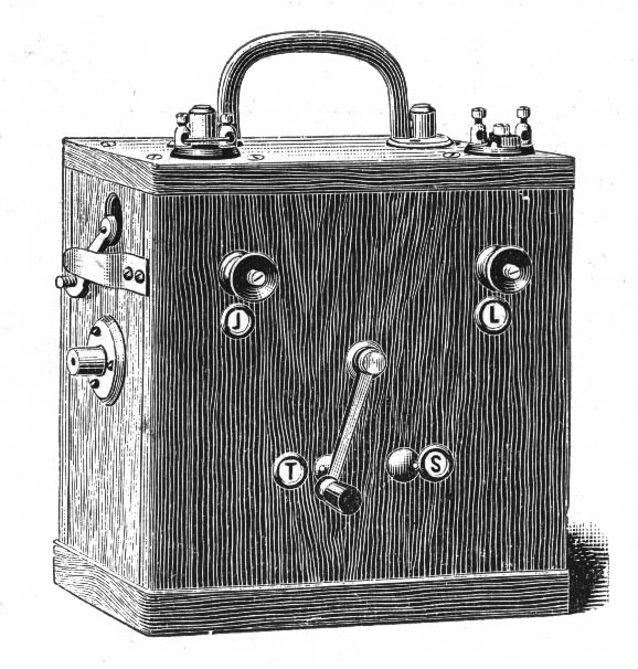
Testing-set
intended for line-men and fault-finders. This instrument is provided with generator, bell, and terminals for receiver line and earth. When ringing, the switch should be placed on S and when speaking on T. The receiver also serves as transmitter. Weight 4,15 ko.
Combination-sets.
These sets, made either of aluminium or nickel plated metal, are, to suit the construction of the instruments with which they are used, with or without a key in the handle for completing the primary circuit and in some cases with an eye for suspending it on the switch-hook.
For switch-boards of latest construction the receiver is differentially wound and a third terminal is added for earthing it and the middle point. The set is generally provided with a four or five way plug to fit into a corresponding jack in the telephone or switchboard, thus rendering the set easily, changeable.
The mouthpiece is also removable, thus allowing each operator a mouthpiece for her private use.
The following types are at present manufactured.
No. 490
Combination-set
fitted in aluminium with battery key and four-way cord plug and jack.
No. 495
Similar to No. 490, but without plug and jack. Intended for table-sets.
No. 500
Similar to No. 490, but with differently wound receiver, five way cord, plug and jack.
No. 505
Same as No. 500 but without key.
No. 510
Same as No. 505 but with eye for suspending.
No. 515
Combination set
fitted in nickel-plated metal with battery key and four-way cord plug and jack.
No. 520
Similar to No. 515, but without plug and jack. Intended for table-sets.
No. 530
Same as No. 520, with four way plug eye for suspending, but without key
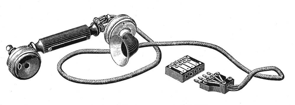
Breastplate Transmitter with Head Gear Receiver.
This arrangement will be found very convenient for busy central station work, where it is desirable for the operator to have both hands free. The key for the primary circuit is placed beneath the transmitter and by moving the small arm to either side, two positions and different modes of connections are obtained. In the one the key has to be depressed to make the primary circuit, and in the other the key is kept down thus securing a constant connection. The advantage of this arrangement is that it spears the battery. When the operator is not too busy, she releases the key and only keeps it down while speaking.
The plate, transmitter and receiver are all made of aluminium, which somewhat reduces the weight.
The transmitter can be turned, by which the mouthpiece may be adjusted to any suitable distance to the mouth. The mouthpiece is removable. When the operators are very busy the primary key is replaced by a spring arranged so, that the current is connected when the mouthpiece is in the ordinary speaking position, but disconnected when the transmitter is turned back, the frame is thus completely insulated and does not as in the other, serve as conductor.
No. 535 & 536

Breast-plate-set
with hand-gear receiver and four-way plug and jack.
Weight 0,64 ko.
No. 540 & 541
Breastplate-set with differentially wound head-gear receiver and five-way plug and jack.
No. 545
Receiver
without conducting cord. Weight 0,35 ko.
No. 546
Receiver with cord.
No. 547
Receiver without ditto [cord]. Weight 0,36 ko.
No. 548
Receiver with cord.
No. 549
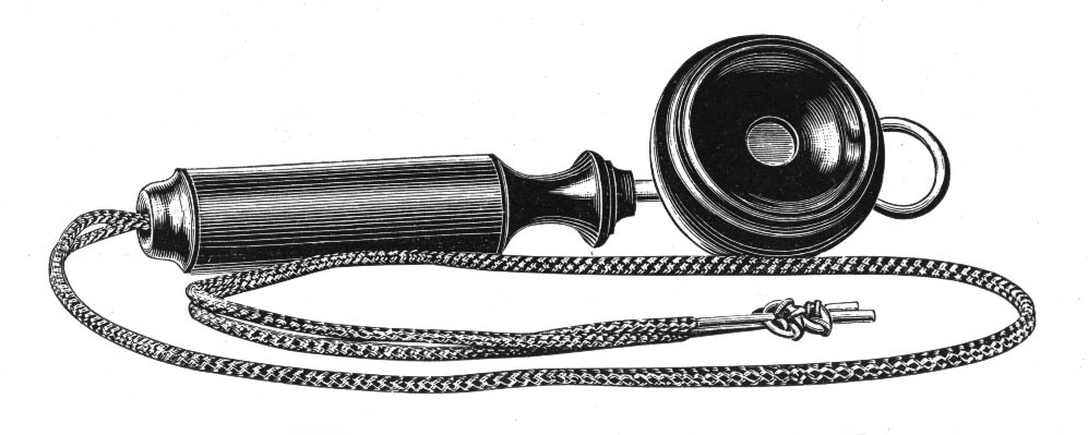
Handle-receiver of the same strength and construction as those in the combination-set with cord.
No. 550
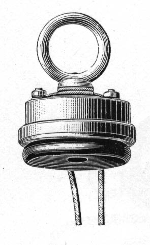
Box receiver
with conducting cord. Weight 0,17 ko.
No. 551
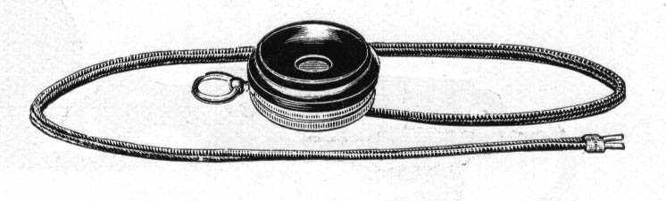
Box receiver with cord. Weight 0,17 ko.
No. 552

Pocket receiver with cord. Weight 0,30 ko.
No. 570
Carbon-grain transmitter
for use on telephones of our manufacture. Weight 0,26 ko.
No. 575
Carbon-grain transmitter with bracket for substituting the Blake transmitter on Bell-telephones. Weight 0,30 ko.
No. 576
Carbon-grain transmitter for the same purpose as No. 575. Weight 0,30 ko.
No. 580
Carbon-grain transmitter for substituting the Ader transmitter on combination-sets. Weight 0,15 ko.
Connection descriptions
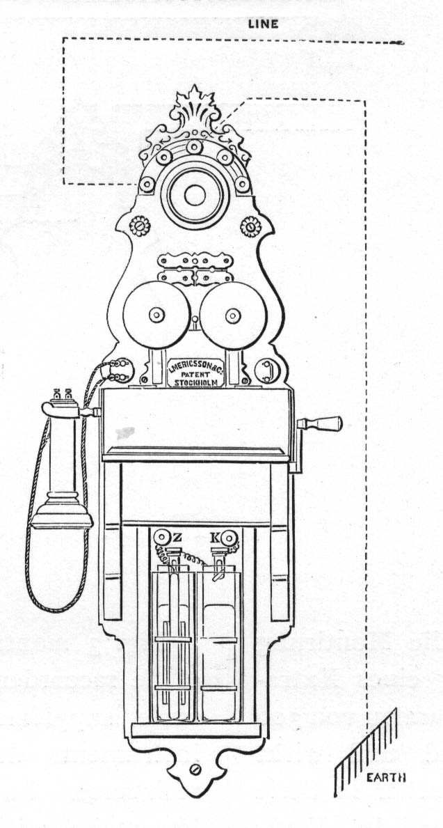
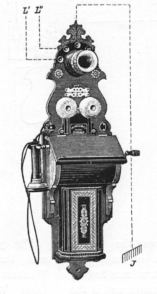
Fig. 1 shows how to connect a single and Fig. 2 a metallic circuit with the instruments No. 301-320.
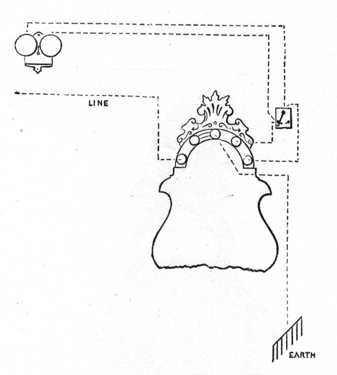
Fig. 3 shows the fitting and connection of an extension bell to instruments having 300 ohms resistance and is the extension bell here working in series with the bell of the telephone. Bells No. 425 or 430 are used.
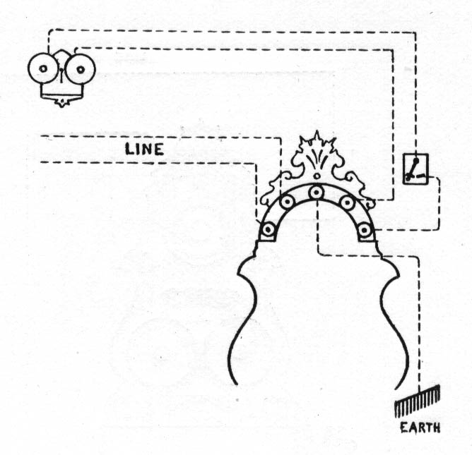
Fig 4. The fitting of an extension bell to instruments having 1,000 to 2,000 ohms resistance and is the bell here shunted across the line. Bells No. 426, 427, 432 or 433 are used.
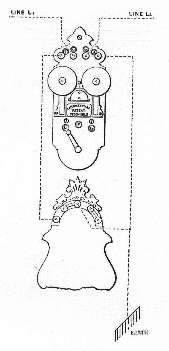
Fig. 5 shows the connection of the junction-switch No. 435 for two single lines on terminal instruments.
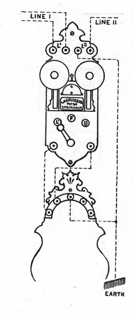
Fig. 6. The connection of the switch No. 440 for one single and one metallic circuit.
When used for two metallic circuits the connections are the same except that the return for Line II is connected with the second terminal at L2 instead of the earth connection.
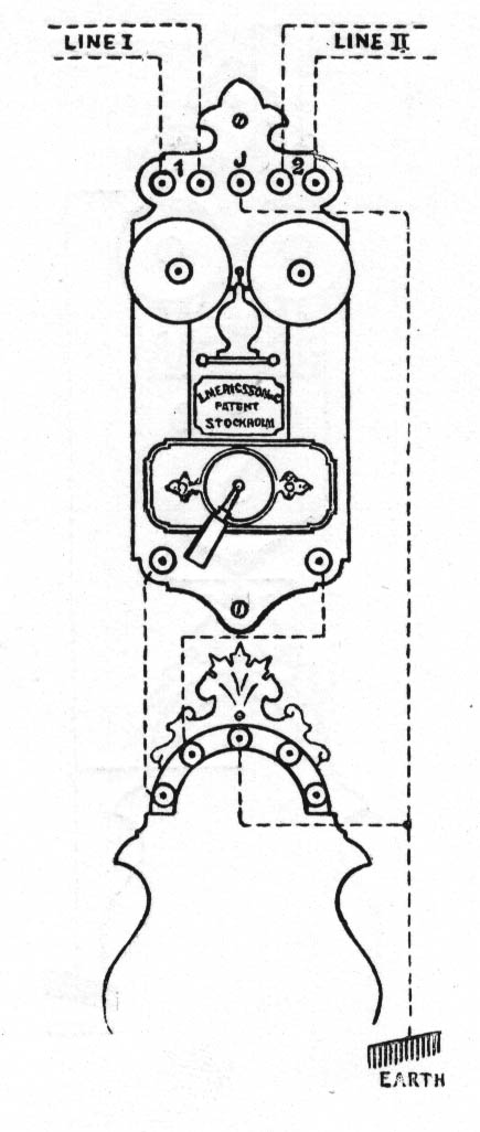
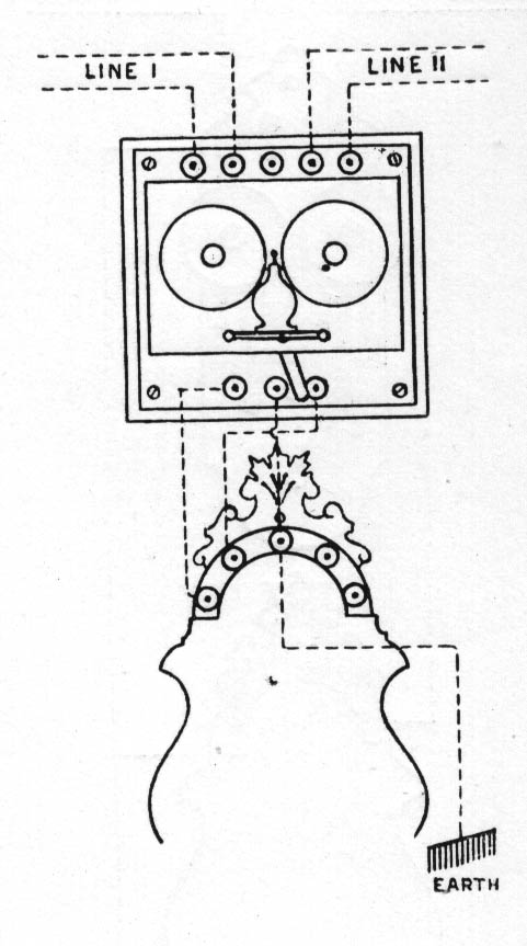
Fig. 7 shows the connection and fitting of the switch No. 450 and fig. 8 those of No. 455, both used for two metallic lines at terminal station telephones.
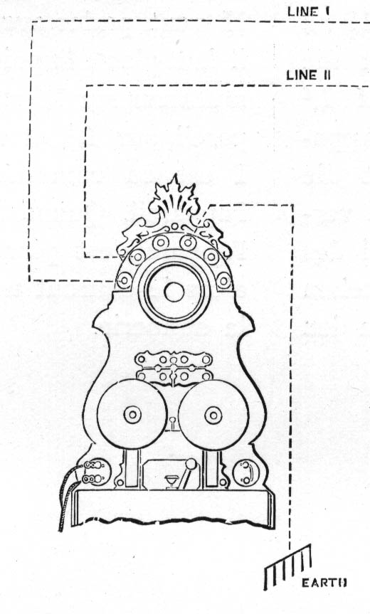
Fig. 9 shows how to connect lines with the intermediate-station telephone No. 325 used for two single lines.
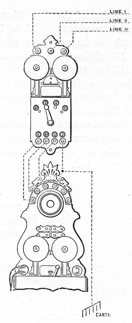
Fig. 10 shows the connection and fitting of the switch No. 460 to the intermediate-station telephone No. 325. The handle should be on S in its resting position and a signal from the third line now rings the bell on the switch. For speaking to this line the handle is placed on 0 and that of the telephone vertically. If line III wishes to speak to line I, the handle of the switch is placed on L1 and that of the telephone on L2 and then line II is connected with the instrument. If line II wishes to speak to line III, the handle of the switch should be placed on L2 and that of the instrument on L1 and then line I is connected with the instrument. If the handle of the instrument is left in the middle, the current does not ring the bell.
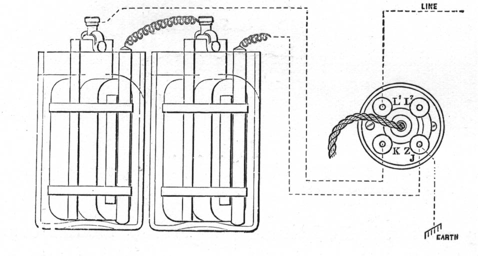
Fig. 11 shows the connection and fitting of the wall rose to the table-sets. If used for metallic circuits the return wire is put on to L2 and the connection between L2 and ZJ is taken away.
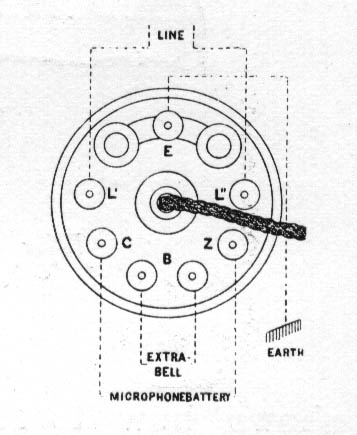
Fig. 12. Shows the fitting of the battery, extension bell, lines and earth to the wall rose of the latest pattern.
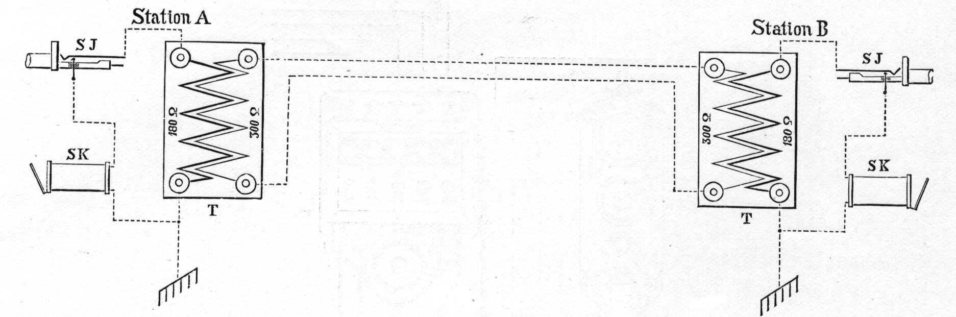
Fig. 13 shows the connection of the translator No. 615 when used between single and metallic circuits.
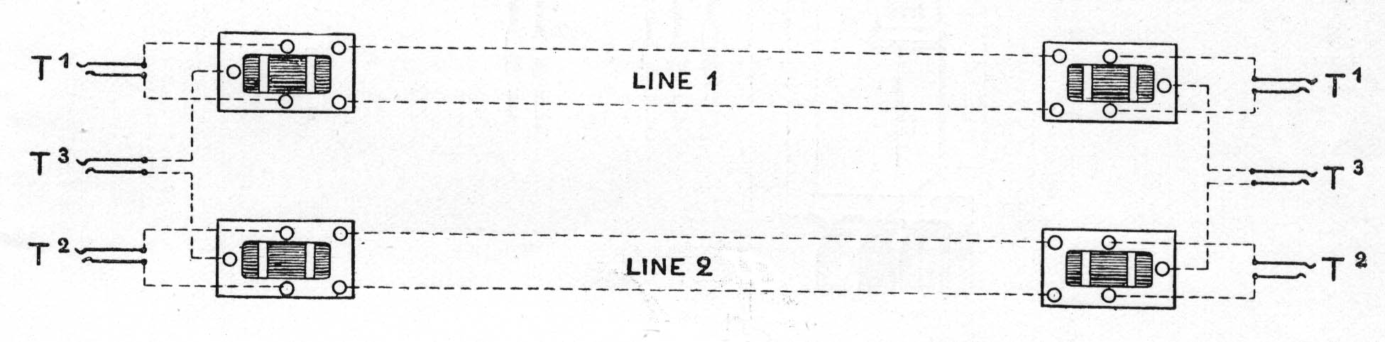
Fig. 14 shows the connection of the translator No. 620 when used for duplex transforming.
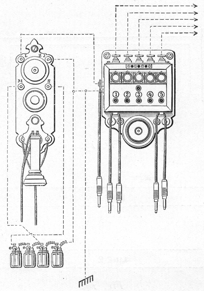
Fig. 15
Directions for fitting the switches No. 467 - 472 with a galvanic telephone instrument
The line of the telephone is connected with the cord plug of the left side of the switch and with the unnumbered jack hereinafter named the operating jack.
The terminal screws on either side of the bell are intended for receiving the wires from an extra battery for the signal bell, which is sounding without interruption as long as a signal drop is down and the plug is remaining in the middle hole of the commutator on top of the frame of the box.
If a signal arrives from the line No. 1 the corresponding drop falls down.
A plug for instance the left pair of cords is introduced into the jack No. 1 and the other plug of the same pair into the operating jack, when messages can be sent from the telephone apparatus to the subscriber No. 1. As only the sphere of the one plug of a pair of cords is conducting connection with the cord, the advantage is obtained that only on signal drop enters into the circuit for the ring off signal.
When calling from the telephone belonging to the switch, the operating plug is used, which is put into the line jack of corresponding subscriber.